can i use 3d drawing for cnc machining
Modern CNC machining organization is able to translate parts geometry direct grade 3D CAD design files. Although Technical drawings is not necessary for quotation request, information technology is still very important and widely used in industry, in club to improve communication of technical requirements between designers and engineer or machinist. We recommend you to prepare a technical drawing in you CNC order, and guarantee our smooth cooperation in farther stride.
.
Why Technical Drawing is Important
Every bit your technical drawing in society ever including post-obit element:
Threads (internal or external)
Feature with exceed standard tolerance
Individual surface with specific finishes
All these requirement is difficult to transfer in 3D CAD file. Even your CNC design doesn't involve the above chemical element, it is a fantabulous practice to back-trail 3D CAD file with technical cartoon one time place a CNC order. The 3D CAD file is applied for CNC machine programming, and technical drawing is practical for machining process reference. Every bit most CNC service providers prefer technical cartoon over 3D CAD files in reason of:
- They are trained to interpret parts geometry form 2D drawing.
- It is easier to identify parts main dimensions, function and critical features class 2D drawing.
- It is easier to assess parts manufacturing toll.
There are different standards and practices for technical drawing draft, the main focus is to communicate clearly most the technical requirements. Equally in this article, all our case drawing is recommended not necessary. You can annotate your most important feature to be measured in technical cartoon.
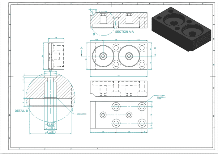
Technical drawing beefcake
A typical technical drawing consist of following parts:
- Championship bock
- Isometric or pictorial part view
- Primary orthographic part view
- Section or detail view
- Notes of manufacturer
Title block
Title block contains bones information of part, including part proper name, textile, finishing and colour requirements, designer name and company. All these data will inform manufacturer nigh part role. Other technical information, such as drawing scale, dimension and tolerance standard. Bending projection is another element in championship cake, which make up one's mind the view manner and arrangement in drawing. Typical drawing drafts use ASME standard of 3rd angel projection and ISO/DIN standard of ist bending projection.
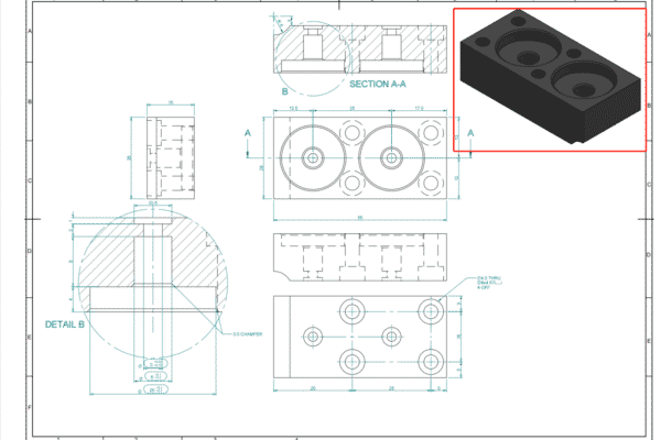
Isometric or pictorial view
Nosotros recommend you to add one or more 3D pictorial views to your drawing, which makes your drawing easier to understand.
Isometric views combine illusion of depth with undistorted presentation, vertical lines remain and horizontal line at 30 degree.
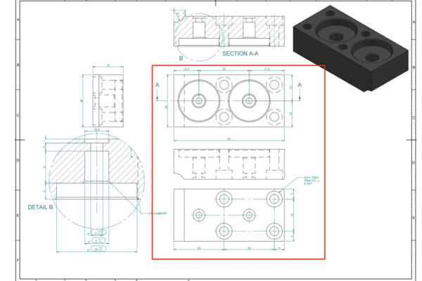
Principal orthographic view
Most geometry information is transferred in main orthographic views. These two-dimensional depictions of 3D object stand for the exact shape of parts course one side at in one case. All parts edges are drawn in this mode to clarify advice of dimensions and features. For most parts, ii or iii orthographic views can depict whole geometry accurately.
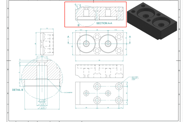
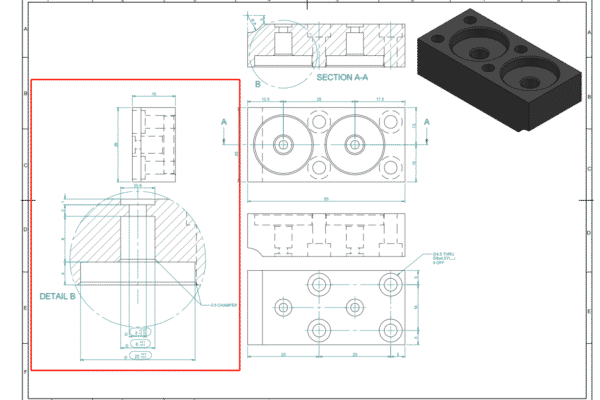
Department view
Section views are applied to nowadays parts internal details, cutting lines in main orthographic view show parts cross-section area, and cantankerous-hatch pattern in department view indicates material removal regions. In that location are multiple section views with two letters linking each cutting line in each department view, such every bit A-A, B-B. Cutting line arrows indicate your vision directions. Although hidden internal features tin be represented with dashed lines in orthographic view, section views will make it more than clear.
Detail view
Detail views are applied to highlight circuitous or difficult dimension areas in main orthographic views. They are typically placed outset to avoid confusion, and annotated with unmarried letter links detail view with primary drawing similar A, B and so on. Detail views can be placed anywhere on drawing with different scale to clarify communication.
Notes for manufacturer
Notes of manufacturer can convey additional information, which is not included in technical drawing. Such every bit: instructions of precipitous edges break or dedurr, specific surface stop requirement.
Sometimes symbols are practical instead of text.
Technical Cartoon in 7 Steps
One time you lot program your technical drawing draft, here is a summary of following steps:
- Define the most important views and identify relevant orthographic in the center of cartoon, left space to add together dimensions.
- For internal features or circuitous and difficult to dimension area, add together section views or detail views accordingly.
- Add construction line to all views, including center lines, heart marks, center mark patterns.
- Add dimensions to drawing, starting form the about important dimensions.
- Specify all threads location, size and length.
- Add together tolerance to features with high accuracy than standard.
- Fill title cake, guarantee all relevant information and exceed standard requirement in notes.
When your drawing is finished, export a PDF file and adhere it to your order.
Regardless this basic structure of technical drawing, nosotros also need to specific of dimensions, annotations and tolerances.
Dimensions, Tolerance& Annotations
Critical dimensions
Once you parts design is accompanied with 3D CAD file, the dimensions on technical cartoon must be critical for manufacturer to check. Especially for important features, in gild to avoid errors in manufacturing procedure.
Tips of critical dimension brandish:
- Placing overall dimension of parts.
- Add critical dimensions for functional purposes.
- Add together dimension to other features, starting form same baseline.
- Dimensions should be placed on views with most clear description.
- For repeated features, add merely ane of them, and indicate the total number of repeat features in electric current view.
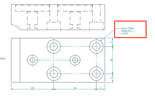
Hole callouts
Holes are common features in CNC machining, and usually machined by drill slots with standardized dimensions. Secondary features, similar cunterbores (⌴) and countersinks(⌵), we recommend to add a callout instead of private dimensions. In the case below, the depth symbol (↧) is used to instead of an boosted dimension to cartoon.

Thread
Once your parts contain threads, these features must be clearly specified on technical cartoon. Threads tin be defined by simply standard thread size like M4 instead of a bore dimension. We recommend to define threads through callout, it tin not only add clarity to drawing, but as well specific different length of pilot holes and threads. In this case, we should define pilot hole dimensions from standard tables at first, and then thread dimensions and tolerances.
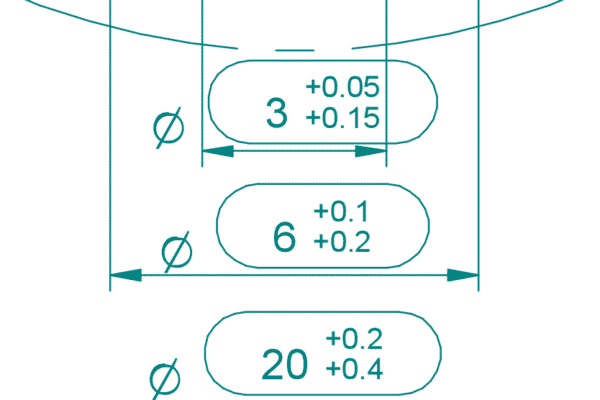
Specifying tolerances
Tolerances define acceptable value range for certain dimensions of parts, which are especially important for feature interfere with other components. Tolerances have different formats with and tin be applied to whatever dimension both linear pismire athwart on drawing. The simplest tolerances are bilateral tolerances, which are symmetrical around base dimension as±0.1 mm. There are besides unilateral tolerances and interference tolerance in technical tabular array.
Tolerances are only required once exceed standard value, our CNC machining standard tolerance is ±0.125 mm or ±0.005".
Runsom recommend technical drawing once your parts contain threads, tolerance or specific surface finishes. Fully dimension is required to avoid errors.For more particular information, contact our engineering squad for your next project.
harringtoncheyetch.blogspot.com
Source: https://www.runsom.com/technology/technical-drawing-for-cnc-machining/
0 Response to "can i use 3d drawing for cnc machining"
Enviar um comentário